Drone-Based Radar VCO Design
Download Final Report (PDF)Author: Colin Byrne
Institution: Carleton University
Course: Electrical Engineering Final Technical Report
Term: Winter 2026
This project presents the design, simulation, and hardware validation of a voltage-controlled oscillator (VCO) for a 5.4 GHz phase-locked loop intended for a drone-based surveillance radar system.
The project initially investigated a varactor-tuned Colpitts oscillator using ADS and HSPICE-based nonlinear models. Although the varactor approach demonstrated theoretical tunability, practical implementation challenges at microwave frequencies resulted in instability and degraded output performance.
An alternative midpoint biasing approach combined with an op-amp control interface was then implemented and tested. The final design demonstrated improved stability, stronger oscillation amplitude, and better agreement between simulation and hardware measurements.
Radar System Overview
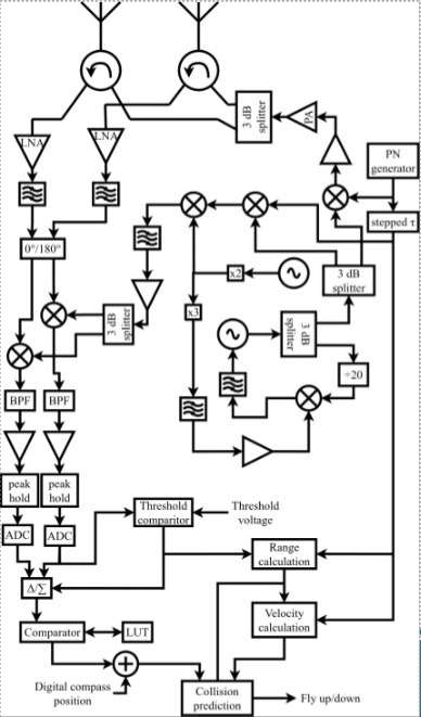
The overall project is a drone-based short-range surveillance radar intended for air traffic monitoring of autonomous delivery drones operating in low-altitude urban environments.
As delivery drone deployment continues to increase, there is growing demand for compact sensing technologies capable of tracking multiple UAVs while operating under strict size, weight, and power constraints.
The radar system integrates antennas, microwave RF hardware, signal processing blocks, and a phase-locked loop responsible for generating a stable microwave reference signal.
Phase-Locked Loop Architecture
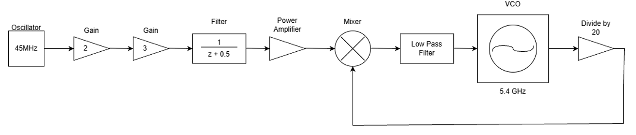
The radar requires a stable low-noise signal around 5.4 GHz for both transmission and reception. This signal is generated using a phase-locked loop (PLL).
The PLL compares a low-frequency reference oscillator with a divided feedback signal derived from the VCO output. The phase error is filtered and converted into a tuning voltage that controls the oscillator frequency.
The PLL subsystem was divided among project members, including:
- Reference oscillator and multiplier stages
- Mixer and divide-by-20 feedback network
- Loop filter implementation
- Voltage-controlled oscillator and tuning circuitry
My primary contribution focused on the tuning subsystem, including varactor modeling, midpoint biasing methods, and op-amp-based control voltage generation.
Varactor-Tuned Colpitts Oscillator
Oscillator Principle
The Colpitts oscillator is a common LC oscillator topology widely used in RF and microwave applications due to its simplicity and frequency stability.
The oscillation frequency is approximately:
\( f_0 = \frac{1}{2\pi \sqrt{L C_{eq}}} \)
where
\( C_{eq} = \frac{C_1 C_2}{C_1 + C_2} \)
The resonant tank consists of an inductor and a capacitive divider, while feedback is provided through the divider network to sustain oscillation.
Varactor Tuning
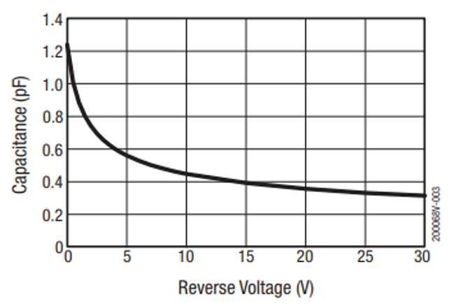
Frequency tuning was initially implemented using a varactor diode whose capacitance changes with reverse-bias voltage.
\( C(V_R) = C_0 (1 + \frac{V_R}{V_j})^{-m} \)
Changing the reverse bias voltage alters the effective tank capacitance and therefore changes the oscillation frequency.
The tuning voltage was generated using an op-amp buffer stage in order to isolate the control circuitry from the RF oscillator nodes and minimize noise coupling.
Technical Challenges
Several technical challenges emerged during the design and simulation process.
One major issue was accurately modeling the nonlinear behavior of the varactor at microwave frequencies. Parasitic series resistance, package inductance, and layout effects significantly affected oscillator stability and output power.
Another challenge involved maintaining stable oscillation across the tuning range while minimizing phase noise and sensitivity to control voltage fluctuations.
The op-amp tuning interface also introduced practical limitations related to bandwidth, slew rate, and output noise. At 5.4 GHz, even small fluctuations in the tuning voltage can produce noticeable frequency instability.
These effects demonstrated the importance of considering system-level parasitics and practical RF implementation constraints rather than relying only on ideal simulations.
Alternative Tuning Methods
Although varactor tuning is widely used in high-performance VCOs, simulation results showed reduced output magnitude and unstable oscillation behavior in the implemented design.
As an alternative, midpoint biasing was investigated by applying the tuning voltage directly to the midpoint of the capacitive divider network.
This approach simplified implementation while producing stronger and more stable oscillation.

Although midpoint tuning introduces trade-offs such as RF feedthrough and reduced isolation, it proved to be a more practical and robust solution within the project constraints.
Design Implementation
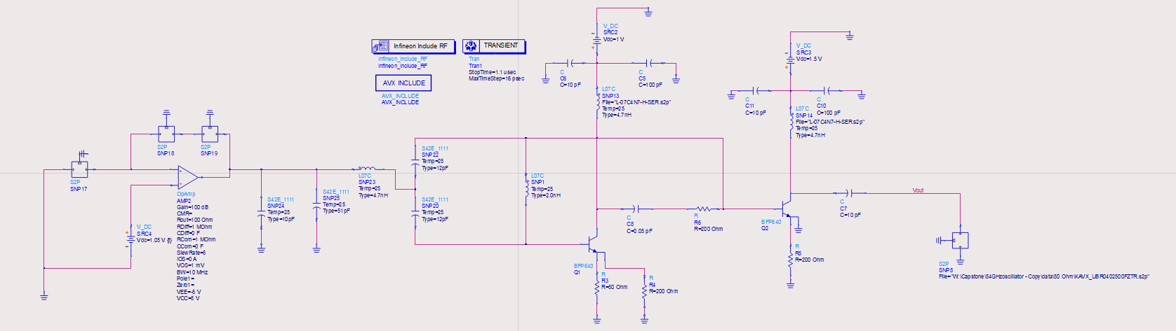
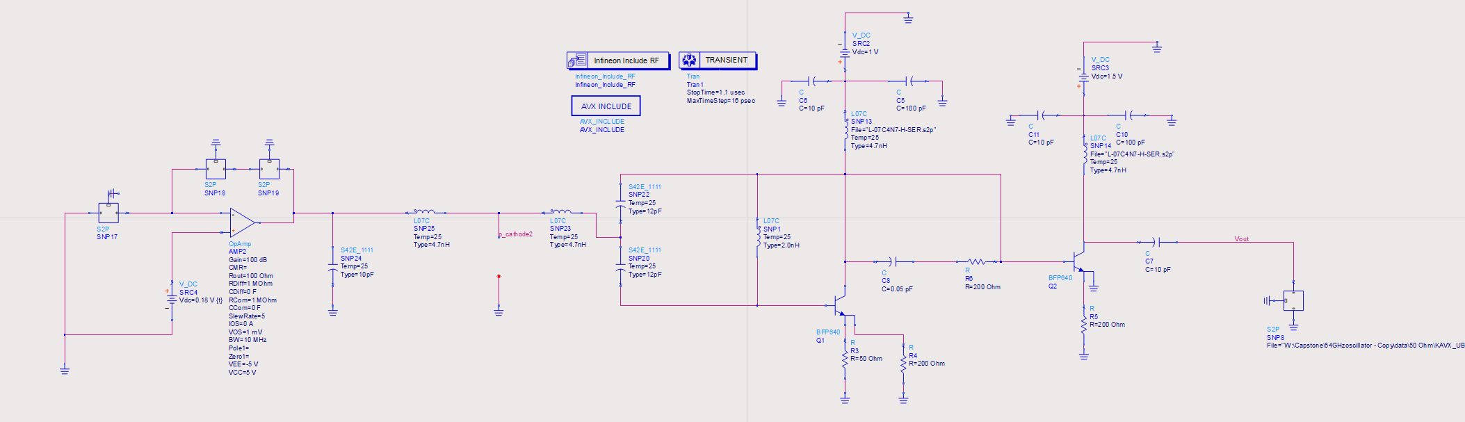
The oscillator and tuning circuitry were developed using Keysight ADS for both schematic-level and electromagnetic simulation.
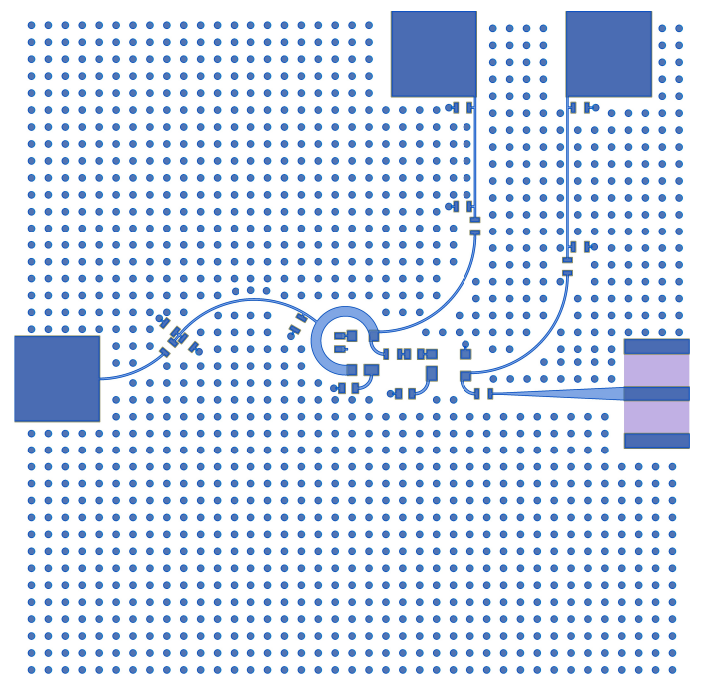
Parasitic effects, transmission line behavior, and layout coupling were analyzed using Momentum simulations prior to PCB fabrication.
The tuning voltage was applied through a high-speed op-amp buffer stage to provide low output impedance and minimize loading of the oscillator tank.
The oscillator was simulated at approximately 6.6 GHz to compensate for expected parasitic detuning effects that would shift the final hardware closer to the 5.4 GHz target.
Hardware Setup
Two oscillator configurations were tested in ADS: a varactor-based design and a midpoint-biased design.
The PCB layout for the oscillator and op-amp sections was developed collaboratively as part of the project team.
Special attention was given to grounding, decoupling, short trace routing, and minimizing parasitic coupling between RF and control paths.
Simulation and Measurement Results
Simulation results showed clear differences between the two tuning approaches.
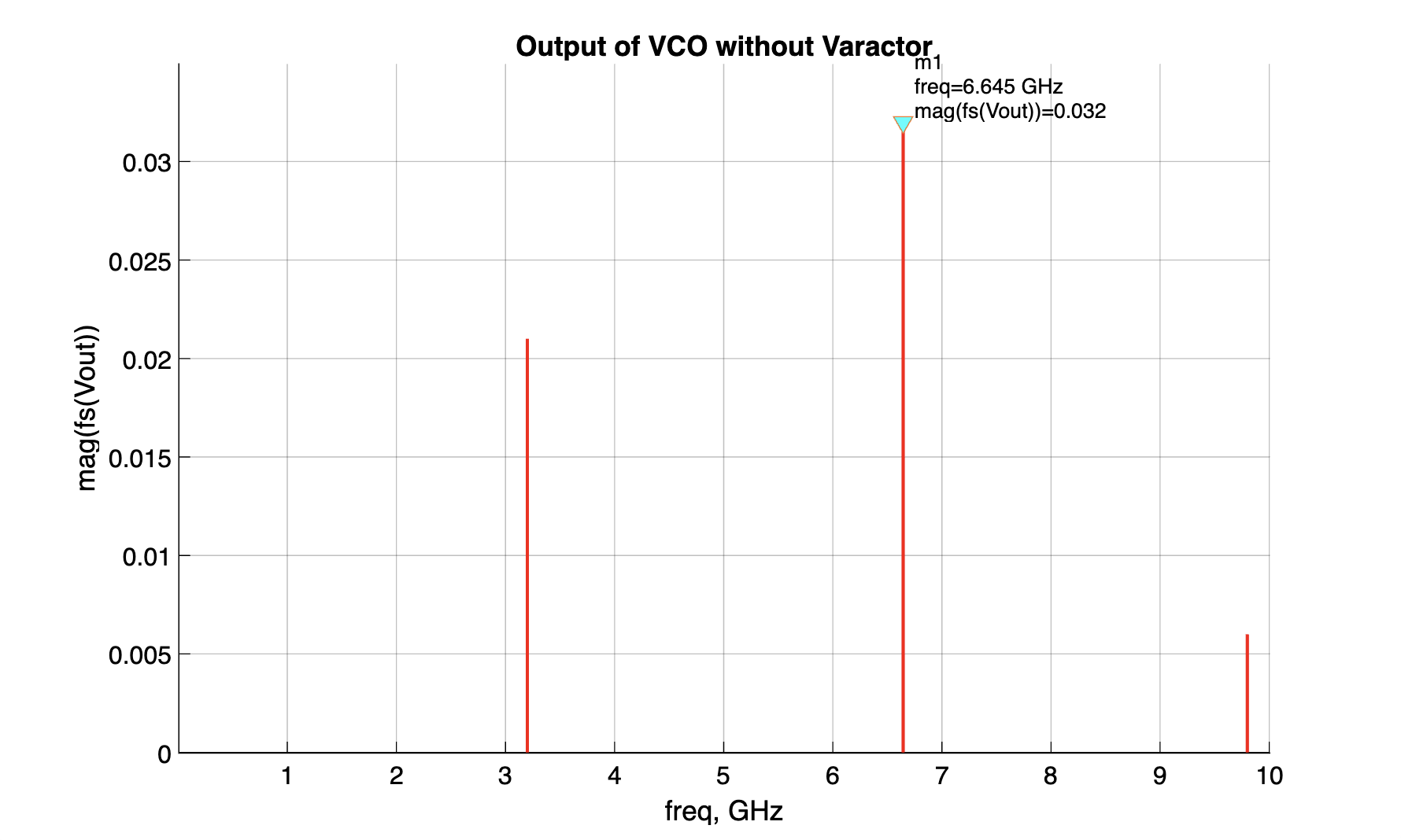
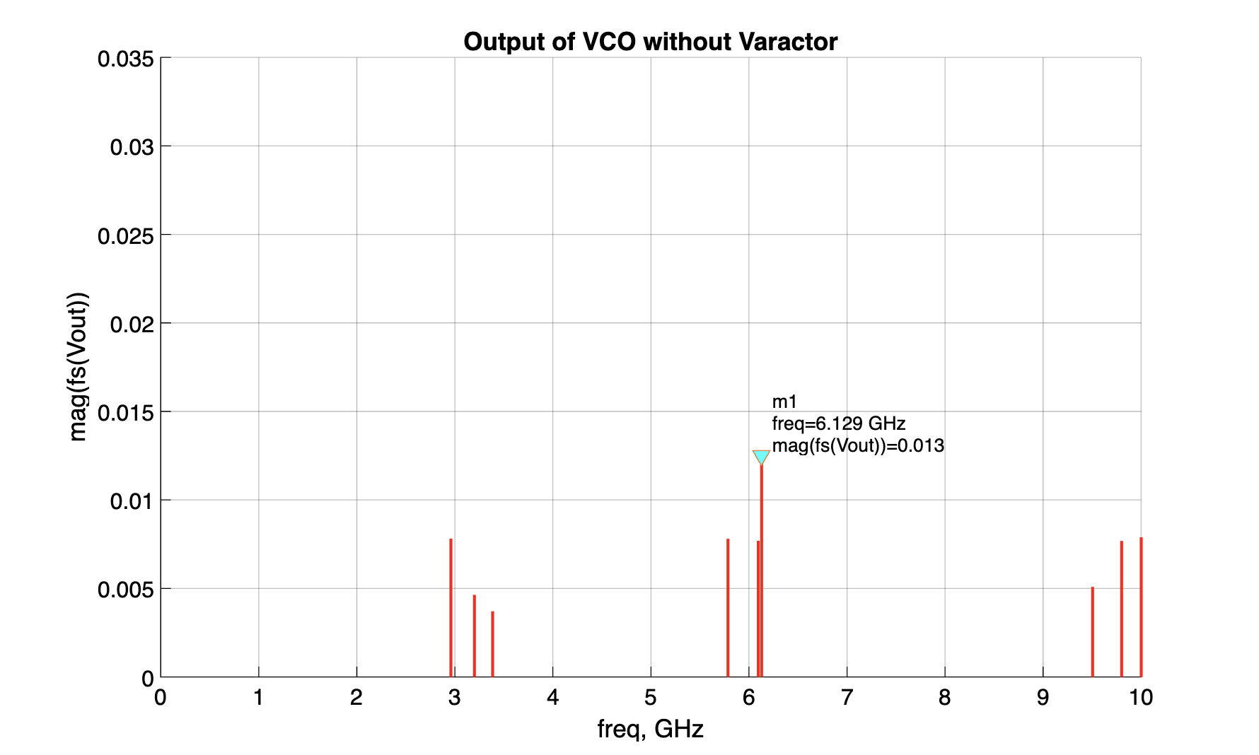
The midpoint-tuned oscillator produced stable oscillation with consistent amplitude, while the varactor-based design showed reduced output power and instability caused by nonlinear and parasitic effects.
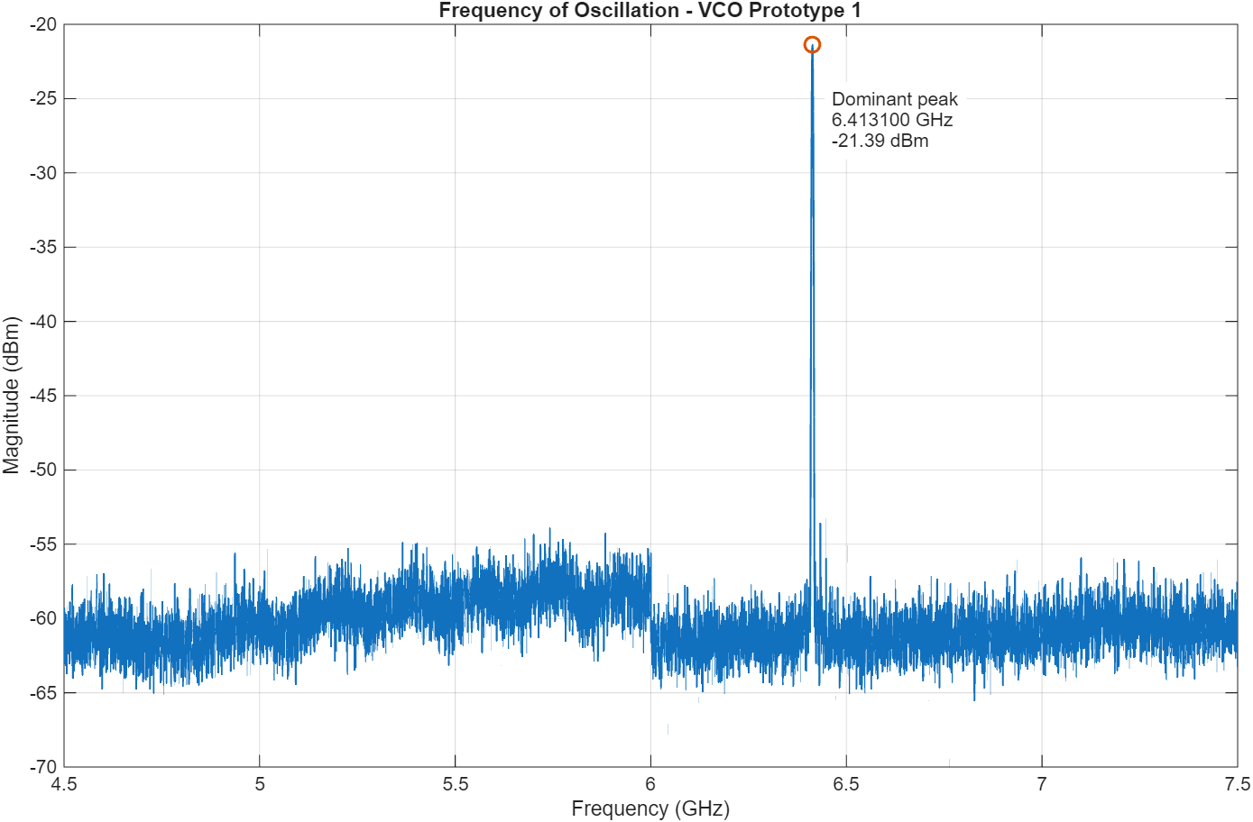
The final hardware results showed stable oscillation with strong amplitude and good agreement with simulation.
Discussion
The instability observed in the varactor-based oscillator was primarily caused by high-frequency parasitic effects, including package inductance, series resistance, and nonlinear capacitance behavior.
These effects reduced the effective quality factor of the LC tank and introduced spurious oscillation behavior.
The midpoint tuning approach avoided many of these issues and provided a more reliable implementation while still allowing practical frequency tuning.
The op-amp testing also demonstrated that bandwidth and slew-rate limitations significantly affect control signal quality, particularly at lower frequencies.
Overall, the project highlighted the importance of practical RF implementation considerations and system-level design trade-offs in microwave oscillator development.
Future Work
- Develop a fully optimized varactor-based tuning network
- Design a custom high-speed op-amp specifically for PLL tuning
- Perform detailed phase-noise characterization
- Improve PCB layout using multilayer RF design techniques
- Integrate the oscillator into the complete radar system
- Perform full PLL lock and stability testing
- Investigate temperature compensation techniques
- Expand electromagnetic simulations for all RF interconnects
Future improvements would allow more accurate frequency control, improved phase-noise performance, and stronger integration with the overall radar platform.
Appendices
Example MATLAB Spectrum Plotting Script
clear; clc; close all;

data = readmatrix('vco_spectrum.csv');

freq = data(:,1);
mag = data(:,2);

figure('Color','w');

stem(freq, mag, 'r', 'LineWidth', 1.5, 'Marker','none');

grid on;

xlabel('freq, GHz');
ylabel('mag(fs(Vout))');

title('Output of VCO without Varactor');

xlim([0 10]);